
Jul 15th 2026
Post-Tensioning Long-Span Architectural Concrete
A conceptual approach to creating longer, thinner concrete elements with improved stiffness and reduced long-term deflection.
Designers and concrete artisans continue to push the limits of architectural concrete. Floating countertops, shelves, fireplace mantels, tables, wall caps, seating surfaces, and other cast elements are becoming longer and thinner than conventional concrete construction would normally allow.
As an unsupported span becomes longer, however, the potential for bending, cracking, and long-term sagging increases. Even a strong concrete casting may gradually deflect under its own weight and any sustained load placed on it.
One possible solution is post-tensioning. This technique places the concrete into compression after it has developed sufficient strength. Although commercial post-tensioning systems use specialized tendons, anchorages, and stressing equipment, the basic principle can also be explored in smaller architectural concrete applications.
This article introduces a possible approach using a concealed structural rib, an internal sleeve, and a tensioned steel rod.
Why Post-Tension a Long Concrete Span?
Concrete performs extremely well in compression but is comparatively weak in tension.
When a long concrete element spans between two supports, gravity causes it to bend downward. In a typical simply supported span:
- The upper portion of the concrete goes into compression.
- The lower portion goes into tension.
- The greatest bending demand often occurs near the middle of the span.
Over time, this may contribute to:
- Sagging or visible deflection
- Concrete creep
- Hairline cracking
- Reduced load-carrying ability
- Permanent deformation
Post-tensioning introduces a compressive force through the length of the concrete. This helps offset some of the tensile stress caused by the weight of the concrete and the loads placed on it.
Potential benefits include:
- Reduced cracking
- Improved stiffness
- Reduced long-term deflection
- Better dimensional stability
- The ability to create a thinner-looking concrete element
Post-tensioning does not eliminate movement completely. The concrete mix, reinforcement, support locations, span, loading, and anchorage details all remain important.
Use a Concealed Structural Rib
A practical way to keep a thin visible profile is to add structural depth only where it is needed.
For example, an architectural element might include:
- A ¾-inch visible top section
- A concealed rib extending ¾ inch below the top
- A total depth of approximately 1½ inches through the rib
From the exposed sides, the finished piece may still appear to be only ¾ inch thick. The concealed rib provides additional depth for stiffness, reinforcement, and the post-tensioning assembly.
The rib can:
- Increase resistance to bending
- Provide space for reinforcement
- Provide room for the tendon sleeve
- Create space for bottom-access pockets
- Add concrete around the anchorage areas
The rib should transition smoothly into the thinner portion of the casting. Abrupt thickness changes may create stress concentrations and increase the risk of cracking.
Creating a Sleeve for the Tensioning Rod
The tensioning rod should not be cast directly into the concrete if it needs to move during stressing.
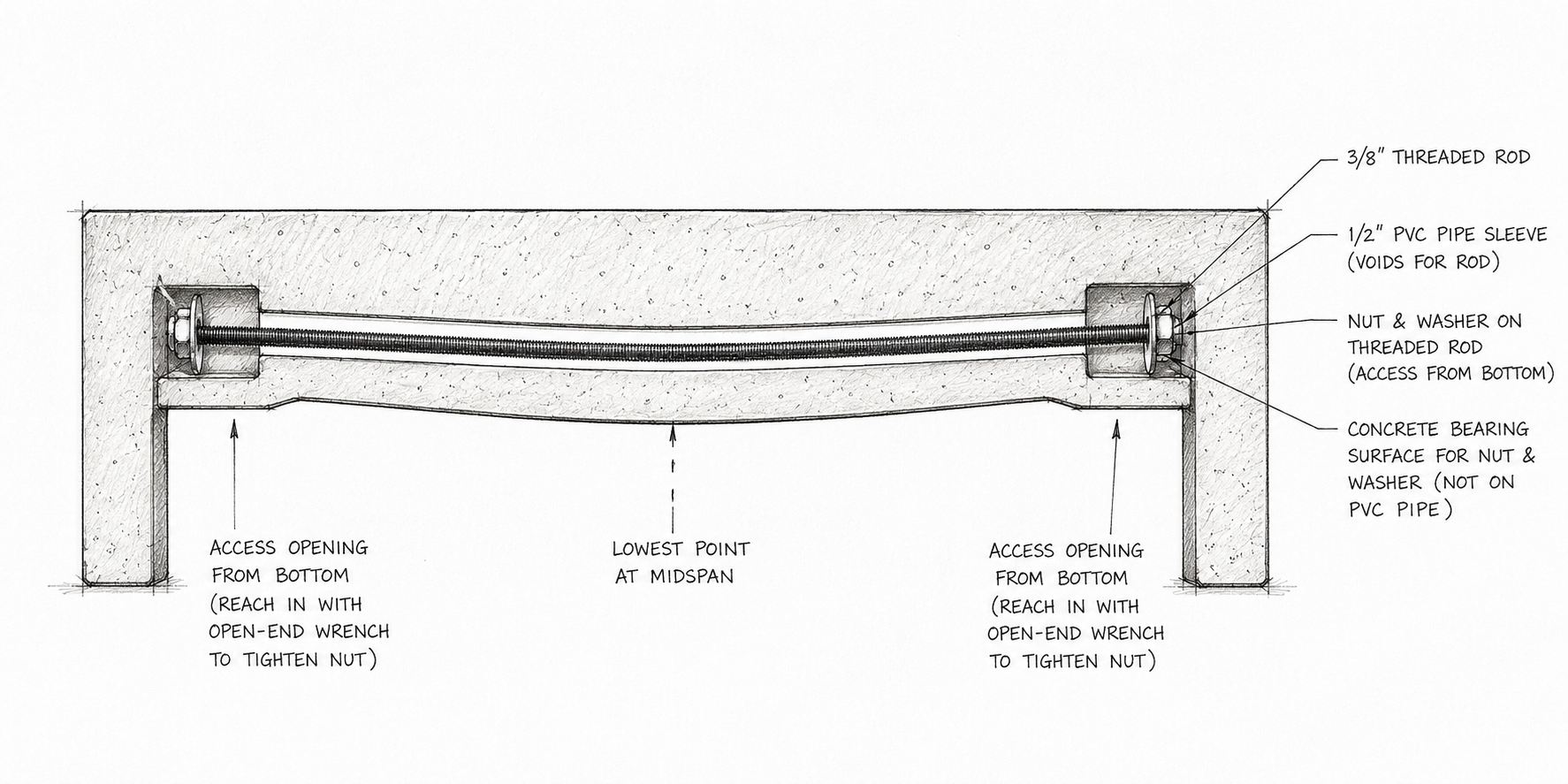
Instead, a smooth sleeve can be positioned through the concealed rib. A properly sized PVC pipe may be suitable for an experimental architectural casting, although purpose-designed post-tensioning ducts are preferred for engineered structural work.
The sleeve:
- Keeps the concrete from bonding to the rod
- Allows the rod to stretch slightly during tensioning
- Keeps the rod clean during casting
- Helps maintain the intended rod position
- May allow the rod to be inspected or replaced
The sleeve should be larger than the rod so that the rod can move without binding. All joints should be sealed carefully to prevent cement paste from entering the sleeve.
The sleeve must also stop before the anchorage area. The nut, washer, and bearing hardware must tighten against solid concrete or an engineered steel bearing surface—not against the end of the PVC pipe.
Protecting the Threaded Ends During Casting
Removable foam blocks or clay can be incorporated into the underside of the mold at both ends of the rod.
The foam protects the threads during casting and creates access pockets that can be opened from the bottom after the concrete has cured.
A conceptual installation sequence is:
- Build the mold and concealed rib.
- Secure the PVC sleeve in position.
- Insert the threaded rod through the sleeve.
- Place removable foam blocks or clay around both threaded ends.
- Seal the sleeve and foam carefully.
- Cast and consolidate the concrete.
- Allow the concrete to reach the required strength.
- Remove the foam or clay from the underside.
- Install the washers and nuts directly onto the threaded rod.
- Apply tension gradually and carefully.
The access pockets must be large enough to install the hardware and operate an open-end wrench. At the same time, they should not remove so much concrete that the ends become weak.
Concealed Access from the Bottom
Bottom access allows the visible ends of the concrete to remain clean and uninterrupted.
After the foam blocks or clay are removed, the installer reaches upward through the access pockets to place the washer and nut directly onto the long threaded rod.
The basic force path is:
Nut → hardened washer or bearing plate → concrete anchorage area → compressed concrete element
Bottom access provides several advantages:
- No exposed hardware on the visible ends
- Cleaner architectural appearance
- Protected rod ends
- Ability to inspect the hardware
- Potential for future adjustment
Straight or Draped Rod?
The position of the rod affects how efficiently it helps control bending.
Straight and Centered
A straight rod placed near the center of the section mainly compresses the concrete uniformly.
This may help delay cracking, but it provides less resistance to sag because the force acts close to the center of the concrete section.
Straight and Below Center
A straight rod positioned below the center of the rib is generally more effective.
Because the rod is below the center of the section, the tensioning force creates a slight upward bending effect that helps oppose downward deflection.
For a shallow architectural casting, this is often the most practical arrangement.
Draped or Bowed
A draped rod rises toward the ends and reaches its lowest point near the center of the span.
This shape can more closely follow the bending stresses in a simply supported element and may provide better resistance to sagging.
However, a curved profile requires:
- More rib depth
- A smooth bend
- Adequate concrete cover
- Enough clearance around the sleeve
- Careful control of friction
With a total rib depth of only about 1½ inches, there may not be enough room to create a useful curved profile. In that situation, a straight rod positioned as low as practical within the concealed rib may be the simpler and more dependable choice.
Choosing the Right Threaded Rod
The threaded rod is one of the most important parts of the system.
The rod must stretch slightly as it is tightened. This elastic stretch is what produces the tension in the steel and the compression in the concrete. The goal is not to prevent all stretching, but to keep the rod safely below the point where the steel permanently deforms.
Ordinary low-strength hardware-store threaded rod may not be suitable because it can:
- Stretch permanently
- Lose tension over time
- Have inconsistent strength
- Yield or damage its threads
- Provide unpredictable performance
Whenever possible, use a purpose-designed prestressing bar system with matching nuts, plates, and published stressing information.
For experimental prototypes, a certified high-strength threaded rod such as ASTM A193 Grade B7 may provide better performance than common mild-steel all-thread. However, B7 rod is not the same as commercial low-relaxation post-tensioning steel and should not be treated as a direct substitute for an engineered prestressing system.
The complete assembly should include:
- Certified high-strength rod
- Grade-compatible nuts
- Hardened washers
- Properly sized bearing plates
- Solid concrete behind the bearing area
Rod capacity should be based on the reduced tensile area at the threads, not simply the outside diameter of the rod.
Bearing Plates and Washers
The nut should not tighten directly against the concrete or against a thin standard washer.
The force at the end of a tensioned rod can be substantial. A hardened washer and steel bearing plate help spread this force into a larger area of concrete.
Without adequate bearing area, the concrete may:
- Crush beneath the washer
- Split near the end
- Spall around the access pocket
- Lose tension as the hardware settles
The anchorage area may be more critical than the strength of the rod itself. Bearing-plate size, thickness, and surrounding reinforcement should be determined for the expected tensioning force.
Controlling and Checking the Tension
Torque can provide a rough indication of rod tension, but it is affected heavily by friction between the threads, nut, washer, and bearing plate.
A more dependable system considers both:
- The applied tightening force
- The measured elongation of the rod
The amount that a steel rod should stretch can be calculated from its length, tensile area, material properties, and intended force. Comparing the calculated stretch with the actual measured stretch can help confirm that the rod is behaving as expected.
For a simple prototype:
- Use consistent, specified thread lubrication.
- Tighten the nuts gradually.
- Apply tension in small increments.
- Measure deflection and rod elongation where practical.
- Stop immediately if the concrete cracks, crushes, or moves unexpectedly.
Do not simply tighten the rod as much as possible. Excessive tension can strip the threads, permanently stretch the rod, crush the anchorage area, or cause a sudden failure.
Maintaining Tension Over Time
Some post-tensioning force will naturally be lost over time due to:
- Concrete shrinkage
- Concrete creep
- Steel relaxation
- Seating of nuts and washers
- Compression of the bearing area
- Temperature changes
Belleville washers, also known as disc springs, may help maintain bolt preload in certain engineered assemblies by allowing a small amount of spring movement.
However, they should not be viewed as a simple solution to all long-term tension loss. The washer type, spring rate, stacking arrangement, and initial compression must be matched to the required force.
For most readers, the key point is that long-term tension retention should be considered during design and prototype testing. The access pockets may also allow the rod tension to be checked or adjusted later, provided this is part of the original design.
Stress Only After the Concrete Is Ready
The rod should not be tensioned until the concrete has developed sufficient strength.
A fixed number of curing days is not enough by itself. Strength development varies with:
- Mix design
- Water content
- Temperature
- Curing conditions
- Admixtures
- Casting thickness
Tensioning too early may cause:
- Cracking around the anchorage
- Crushing beneath the bearing plates
- End splitting
- Permanent deformation
- Sudden release of the rod
Concrete strength should be verified with companion test specimens or another appropriate testing method before stressing begins.
Recommended Concrete Mix: UltraCast 360
Advanced long-span architectural elements require a dense, consistent, high-performance concrete mix.
For this type of project, we recommend UltraCast 360 Concrete Mix.
UltraCast 360 is designed for high-performance architectural castings where strength, surface quality, flow, and particle packing are important. Its broad particle-size distribution helps produce a dense concrete matrix with excellent mold reproduction and reduced surface voids.
Potential applications include:
- Long countertops
- Floating shelves
- Fireplace mantels
- Tables
- Wall caps
- Architectural seating
- Thin panels
- Furniture components
- Custom precast elements
UltraCast 360 provides an excellent foundation for advanced casting, but the concrete mix alone does not determine structural capacity. Performance also depends on proper mixing, reinforcement, curing, section geometry, support conditions, anchorage, and tensioning force.
Conventional Reinforcement Is Still Required
Post-tensioning should not be considered a replacement for all other reinforcement.
Additional reinforcement may be required to resist:
- Shrinkage cracking
- Handling stresses
- Impact
- Local anchorage forces
- Shear
- Torsion
- Cracking before the rod is tensioned
Depending on the project, reinforcement may include:
- AR glass fibers
- PVA fibers
- Carbon-fiber grid
- AR glass scrim
- Stainless steel reinforcement
- Conventional reinforcing steel
- Local reinforcement around access pockets and anchorages
The reinforcement must be positioned so that concrete can flow and consolidate around the sleeve, rib, and anchorage areas.
Build and Test a Full-Size Prototype
Any new post-tensioned architectural concrete system should be considered experimental until its performance has been verified.
Prototype testing should include:
- Full-size dimensions
- Actual support locations
- The proposed concrete mix
- The final reinforcement layout
- The complete sleeve and rod assembly
- The actual access pockets and bearing plates
- Measured deflection before and after tensioning
- Sustained-load testing
- Inspection for cracking or crushing
- Long-term monitoring
A small test sample may not accurately represent the behavior of a longer or thinner full-size casting.
Important Safety Warning
A tensioned steel rod stores considerable energy.
If the rod, nut, washer, bearing plate, or concrete anchorage fails, that energy may be released suddenly and violently.
During tensioning:
- Never stand directly in line with either end of the rod.
- Keep other people away from the stressing area.
- Use protective barriers where practical.
- Wear appropriate eye and face protection.
- Tighten gradually.
- Inspect the concrete and hardware at every stage.
- Use certified materials and properly sized hardware.
Any concrete element intended to support people, overhead loads, or public use should be reviewed by a qualified structural engineer.
Final Thoughts
Post-tensioning offers interesting possibilities for longer and thinner architectural concrete elements.
By combining:
- A concealed structural rib
- A properly positioned sleeve
- A high-strength tensioning rod
- Bottom-access pockets
- Hardened washers and bearing plates
- Appropriate conventional reinforcement
- A high-performance mix such as UltraCast 360
it may be possible to produce a clean, slender concrete element with improved stiffness and resistance to long-term sagging.
For a shallow rib, a straight rod positioned below the center of the section will often be easier to fabricate than a tightly curved tendon. The rod should be selected for certified strength and predictable elastic behavior, and the anchorage must be designed to distribute the tensioning force safely into the concrete.
The goal is not simply to tighten a threaded rod inside a casting. The goal is to create a controlled compression system that works together with the concrete, reinforcement, supports, and overall geometry of the finished element.